


Views: 0 Author: Site Editor Publish Time: 2026-10-24 Origin: Site


Laser welding promises unprecedented speed and minimal heat input against the harsh reality of the fabrication shop floor. This technology is fundamentally intolerant of poor part fit-up. Transitioning from MIG or TIG to laser welding often exposes upstream fabrication inaccuracies. Relying on the welder to fill the gap results in burn-through, underfill, severe porosity, and rejected parts when using a high-energy-density laser. Uneven gaps along a single seam further complicate travel speeds and parameter settings.
To achieve the promised return on investment, fabrication managers must evaluate their current joint preparation standards. You need to understand the strict tolerances required and determine when auxiliary solutions like wire feeders and wobble heads are necessary. These tools bridge the gap between ideal engineering conditions and daily production realities.
Fit-Up is the Bottleneck: Autogenous (no-wire) laser welding requires near-zero gap tolerances (typically less than 10% of the material thickness). Upstream cutting and bending processes must be highly accurate.
Wire Feed is a Tool, Not a Cure-All: Adding cold wire feed increases gap tolerance (up to roughly 1mm depending on wire diameter and wobble settings) but cannot compensate for severely misaligned, uneven, or poorly clamped assemblies.
Clamping Dictates Repeatability: Despite lower overall heat input, the rapid thermal cycling of laser welding requires rigid, consistent clamping to prevent micro-cracking, maintain focal distance, and establish a proven parameter window.
Thickness Dictates Prep Strategy: Understanding laser welding thickness factors is critical; while thin sheet metal requires precise square edges, thicker materials may necessitate specific joint geometries, sub-surface focal adjustments, or multi-pass wire-fed strategies to ensure full penetration.
Traditional Gas Metal Arc Welding utilizes a wide, forgiving arc cone. This arc easily bridges gaps, allowing operators to weave and manipulate the weld puddle over imperfect joints. A handheld fiber laser welding machine operates on entirely different physics. It produces a highly focused, microscopic spot size. If a gap exists, the laser beam simply passes right through it. There is no arc cone to spread the heat. The energy either hits the base metal and creates a keyhole, or it shoots through the void, damaging the fixture below and leaving the joint unwelded.
Fabricators often underestimate how tight these tolerances actually are. A gap that a MIG welder wouldn't even notice will completely halt a laser welding operation. The beam diameter at the focal point is often a fraction of a millimeter. When that beam hits a gap wider than its own diameter, you lose the process entirely.
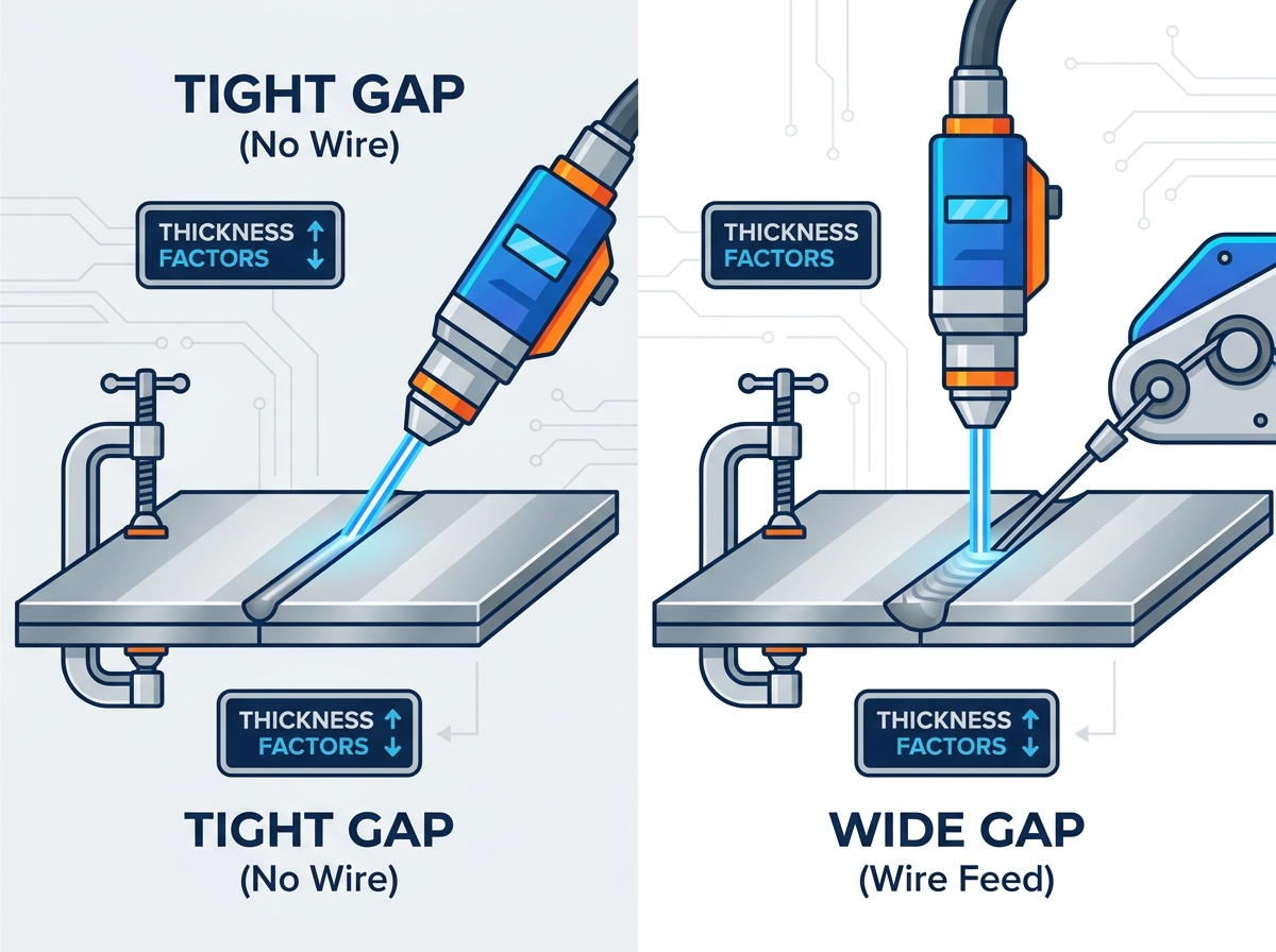
Welding without filler wire is known as autogenous welding. This process demands strict gap limits. Typically, you need a gap of less than 0.1mm, or tight metal-to-metal contact. The metallurgical requirement here is straightforward. You must have sufficient parent material volume to melt and flow together. This creates a flush or slightly convex weld bead. If the gap is too large, the melted material sinks. This causes severe undercutting or a concave weld profile that lacks structural integrity.
Uneven gaps present a specific challenge on the shop floor. A joint might start tight but widen to 0.5mm toward the end of a long run. This variability disrupts the travel speed. An operator moving at a constant rate achieves perfect penetration at the tight end but experiences intermittent burn-through where the gap widens. The laser energy has less mass to absorb it, causing the keyhole to collapse and blow out the back of the part.
Process | Typical Spot/Arc Size | Autogenous Gap Tolerance | Heat Input Profile |
|---|---|---|---|
GMAW (MIG) | 6mm - 12mm | Not Applicable (Always uses wire) | Wide, deep, high total heat |
GTAW (TIG) | 3mm - 6mm | Up to 0.5mm (with manipulation) | Concentrated, high total heat |
Fiber Laser | 0.05mm - 0.2mm | < 0.1mm | Extremely narrow, low total heat |
Manufacturers introduced wobble heads to combat strict fit-up requirements. Modern oscillating laser heads use internal motorized mirrors to manipulate the beam. They move the focal spot in patterns like circles, figure-eights, or infinity symbols. This artificially widens the beam path. By sweeping the beam across a wider area, the wobble head increases gap tolerance slightly, allowing autogenous welding on gaps up to 0.2mm or 0.3mm.
This comes with distinct trade-offs. A wider wobble pattern inherently reduces the energy density at any given microsecond. The laser spends less time concentrated on the root of the joint. To maintain the required penetration depth, operators must compensate. You either need slower travel speeds or higher wattage. Pushing a 1500W laser into a wide wobble pattern on thick material often results in lack of fusion at the root because the energy is spread too thin across the surface.
Poor fit-up connects directly to visual weld defects. If a weld appears rough, oxidized, or unstable, operators often rush to change machine settings. Instead, you must first check joint fit-up and clamping. A gap that fluctuates by just a fraction of a millimeter changes the thermal dynamics of the weld pool instantly.
Verify the gap size using feeler gauges along the entire length of the seam.
Check for burrs or dross from the cutting process that might be holding the joint apart.
Ensure the clamping pressure is even and the part has not bowed in the middle.
Confirm the focal distance is correct; a part that sits too low or too high moves the joint out of the laser's Rayleigh length.
If fit-up is marginal but cannot be improved upstream, operators can adjust parameters to compensate. Increasing laser power helps melt more surrounding material to bridge the void. Decreasing welding speed allows the puddle more time to flow and fill. Verify the focal position. Setting the focus exactly on the surface or slightly below ensures the energy density remains optimal for the specific joint geometry.
When autogenous welding limits are exceeded, fabrication shops must introduce filler metal. Automated cold wire feeders are the primary method for handling real-world fabrication gaps. These systems push a continuous spool of wire directly into the laser's focal point, providing the necessary volume to bridge voids.
Integrating a wire feeder changes the dynamics of the handheld torch. The operator now has to manage the angle of the wire entry, the tension on the drive rolls, and the condition of the contact tip. If the wire speed does not match the travel speed and laser power, the process becomes erratic.
Certain scenarios absolutely require a wire-feed laser welding machine. The most common is bridging consistent gaps between 0.5mm and 1.0mm. The wire melts and fills the void, preventing burn-through on sheet metal assemblies that cannot be perfectly machined.
Wire feed is also critical for modifying weld metallurgy. Welding 6061 aluminum autogenously often leads to hot cracking due to the alloy's specific solidification mechanics. Introducing a 4043 or 5356 filler wire alters the chemistry of the weld pool, preventing these cracks. Structural fillet welds often require a specific throat thickness to meet engineering drawings. Autogenous fillet welds tend to be concave. Adding wire builds the necessary convex profile to meet structural throat requirements.
A wire-feed system is not a direct replacement for the gap-filling capabilities of MIG. It has strict limitations. For massive or highly irregular gaps exceeding 1.5mm, traditional arc welding remains necessary. The laser cannot melt enough wire fast enough to fill massive voids without overheating the base material and causing severe distortion.
The primary risk of using wire feed is cold lap or lack of fusion. This occurs if the laser energy is absorbed entirely by melting the wire rather than penetrating the root of the joint. The melted wire simply sits on top of the cold base metal. Operators must balance wire feed speed with laser power to ensure the keyhole penetrates the root while the wire fills the top.
Adding a wire feeder introduces ergonomic challenges. The operator must manage the added weight of the wire liner. The feed angle becomes critical. The wire must enter the leading edge of the weld pool at a precise angle. If the operator twists their wrist improperly during a long weld, the wire can miss the laser beam entirely, causing the wire to stub into the workpiece and disrupt the process.
Proper fixturing translates directly to weld consistency and defect reduction. It allows fabrication managers to lock in standard operating procedures. Without rigid clamping, the benefits of laser welding evaporate. The process relies entirely on maintaining a stable relationship between the laser nozzle and the workpiece.
Many shops attempt to use their existing welding tables and heavy C-clamps when transitioning to laser. This approach fails because laser welding requires continuous, uninterrupted travel to maintain the keyhole. Clamps that get in the way of the torch body force the operator to stop, reposition, and restart, which introduces defects at every tie-in point.
While the total heat input of a laser is low compared to TIG, the localized temperature gradient is extreme. The weld zone reaches vaporization temperatures instantly, while the metal just millimeters away remains at room temperature. This creates massive localized stress. Parts must be clamped rigidly to prevent warping during the rapid cooling phase. If a thin sheet metal part lifts during welding, the gap opens, and the laser burns through.
Clamping ensures the joint remains at the exact focal distance of the laser lens. The focal depth of a fiber laser is incredibly narrow. Deviations in the Z-axis distance drastically alter penetration. If the part bows upward by 2mm, the laser beam becomes unfocused at the joint surface. The energy density drops, changing a deep keyhole weld into a shallow, wide conduction weld. Consistent clamping guarantees the focal point remains exactly where the parameters dictate.
Traditional heavy clamps are often too slow for high-speed laser cells. Shops must transition to precision toggle clamps, pneumatic fixtures, and copper backing bars. Copper backing serves two purposes: it acts as a massive heat sink to pull temperature out of thin parts, and it provides root shielding to prevent oxidation on the back of the weld.
Laser tacking requires specific best practices to avoid ruining the final weld.
Ensure the joint is clamped tightly with zero gap before initiating the tack.
Set the machine to a high-peak-power, short-duration pulse mode.
Fire the laser for a fraction of a second to create a deep, narrow tack without putting excess heat into the part.
Space tacks closer together than you would for MIG welding to prevent the seam from unzipping during the continuous weld pass.
Traditional TIG tacks often introduce thermal expansion, which pushes the joint apart and creates gaps before the final weld even begins. Laser tacks keep the assembly tight. Rigid, repeatable clamping is the absolute prerequisite for establishing a proven parameter window. Once the fit-up is locked in, engineers can dial in the exact wattage, speed, and wobble settings. Operators can then rely on these settings shift after shift, knowing the physical joint presentation will not change.
Material thickness and joint geometry dictate the required machine power, focal position, and preparation time. You cannot apply the same joint prep rules to 1mm sheet metal that you apply to 6mm plate. Evaluating laser welding thickness factors ensures you select the correct edge profile and focal strategy before striking an arc.
The physics of the keyhole change drastically as material thickness increases. On thin materials, the vapor cavity easily punches through the back side. On thicker materials, the keyhole can collapse on itself if the travel speed is too fast or the focal point is set incorrectly, leading to massive internal porosity.
Thin materials (0.5mm to 2mm) require clean, sheared, or laser-cut square edges. The fit-up must be intimate. For these thicknesses, the focal point is almost always set exactly at the surface level. This maximizes surface energy density, allowing rapid travel speeds while achieving full penetration through the thin cross-section.
Preparation for thicker materials (3mm to 6mm+) shifts significantly. A simple square butt joint may no longer suffice, especially on lower-wattage machines. You may need to transition to a slight bevel to allow the beam deeper access to the root. Keyhole mode penetration behaves differently than shallow conduction mode. To drive the keyhole deep into thick plate, the focal point must often be set slightly below the surface (e.g., -1mm or -2mm). This sub-surface focus ensures the beam stays concentrated as it melts downward, creating deep locking holes.
Material Thickness | Joint Geometry | Focal Position | Wire Feed Requirement |
|---|---|---|---|
0.5mm - 1.5mm | Square Butt / Tight Lap | Surface (0mm) | Rarely needed (Autogenous) |
2.0mm - 3.0mm | Square Butt | Surface to -1mm | Optional (Depends on gap) |
4.0mm - 6.0mm | Square Butt / Slight Bevel | Sub-surface (-1mm to -2mm) | Often required for root fill |
Mixed (1mm to 5mm) | Lap or T-Joint | Surface of thick part | Recommended for fillet profile |
Welding thick-to-thin materials requires specific frameworks. Consider welding a 1mm sheet to a 5mm plate. The primary risk is vaporizing the thin sheet before the thick plate even reaches melting temperature. Preparation requires ensuring intimate contact between the two pieces.
During execution, the operator must direct the laser angle toward the thicker material. The 5mm plate acts as a heat sink. The laser beam should strike the thick plate slightly off the joint line, allowing the conductive heat to melt the 1mm sheet. If the beam hits the thin edge directly, it will blow away instantly. Proper joint design might involve overlapping the thin part onto the thick part to create a lap joint, which is far easier to manage than a mixed-thickness butt joint.
Visual inspection of the top bead tells you nothing about root penetration. During the joint design phase, you must perform a cut and etch test to visually verify penetration depth and profile. This proves your parameters are actually doing the work beneath the surface.
Section the welded joint using a cold saw to prevent altering the heat-affected zone.
Sand the cross-section flat using progressively finer grit paper, typically finishing around 600 grit.
Apply the appropriate chemical etchant (e.g., Nital for carbon steel, Keller's reagent for aluminum) to the polished surface.
Inspect the revealed weld nugget under magnification to measure penetration depth and check for root porosity.
Compare the penetration profiles of fillet welds versus butt welds. A laser fillet weld often looks like a deep spike driving into the root, rather than the wide, rounded nugget of a MIG weld. The cut and etch test ensures the chosen joint preparation, focal position, and laser parameters actually meet the structural requirements of the engineering drawing.
Adopting laser technology requires systemic changes across the entire shop floor. You cannot drop a precision welding tool into a sloppy fabrication environment and expect success. The hidden cost of implementation often lies in upgrading upstream equipment.
Fabricators often buy a laser welder to speed up production, only to find their welding department bottlenecked by the press brake department. If the bending operators are struggling to hit exact angles, the welding operators will spend all their time fighting gaps.
Evaluate the true cost of adoption before purchasing a machine. If a shop relies on manual plasma cutting, abrasive chop saws, or worn press brake tooling, the resulting gaps will render laser welding ineffective. Abrasive saws leave angled, burred edges. Worn press brakes create parts with inconsistent bend angles, leading to massive gaps during assembly.
Audit your current part fit-up. Measure the gaps on your standard assemblies. If gaps consistently exceed 1mm, you must calculate the potential need to upgrade upstream processes. You may need to invest in CNC laser or waterjet cutting, or precision CNC press brakes, just to feed the laser welding station with acceptable parts. A 0.5-degree error on a press brake translates to a massive gap on a 10-inch flange, making autogenous welding impossible.
The transition requires a massive mindset shift. You must train operators to move away from being welders who fill gaps to operators who verify fit-up. A traditional welder takes pride in fixing bad fit-up with a weaving arc. A laser operator must take pride in rejecting bad fit-up before pulling the trigger.
Establish strict visual inspection criteria. Operators must have the authority to reject poorly prepped parts or uneven gaps. Attempting to weld a bad joint wastes gas, wastes wire, ruins the part, and frustrates the operator. Training them to measure gaps with feeler gauges and verify clamping pressure saves time and prevents scrap.
Measure the average and maximum gap sizes on your currently tacked assemblies using feeler gauges to determine if you need a wire feeder.
Audit your upstream cutting equipment to ensure it produces clean, square edges free of heavy dross or burrs.
Send your worst-case fit-up samples to the laser manufacturer for a proof-of-concept test.
Demand a cut and etch validation from the manufacturer to verify their equipment handles your specific joint geometries.
A: Autogenous welding cannot fill gaps. With a wire feeder and wobble head, consistent gaps up to roughly 1mm can be bridged. However, larger or highly uneven gaps typically result in weld failure and require traditional arc welding (MIG/TIG) or hybrid processes.
A: No. Wire is only necessary for bridging gaps, adding reinforcement to fillet welds, or altering the weld chemistry. Precision-cut butt joints with tight fit-up can often be welded autogenously.
A: Material thickness dictates the required laser wattage, the focal position (surface for thin materials vs. sub-surface for thick materials), and whether edge beveling or a multi-pass wire strategy is required to achieve full keyhole penetration.
A: Laser welding is highly sensitive to contamination. Oils, rust, heavy mill scale, and zinc coatings must be removed from the weld zone to prevent severe porosity and spatter.
A: The primary culprits are inconsistent/uneven gap sizes, improper focal distance due to poor clamping, incorrect wire feed speed, or inadequate shielding gas. If fit-up is verified, try increasing power, decreasing travel speed, or adjusting the focus to sit slightly below the surface.
A: No. Laser excels in thin-to-medium sheet metal with tight tolerances. MIG remains superior for heavy structural steel, poor fit-up situations with large gaps, and outdoor environments with wind.


