


Views: 0 Author: Site Editor Publish Time: 2026-10-13 Origin: Site


Operating high-speed laser equipment requires managing high-pressure assist gases, often ranging between 5 and 25 bars. This intense gas flow inherently creates a volatile environment for small, lightweight cut parts. When these small components tip, shift, or blow completely out of the skeletal sheet, they cause immediate and severe production bottlenecks. Tipped parts protruding above the focal plane frequently result in catastrophic equipment damage. Completely detached parts can fall through the cutting bed slats into the scrap drawer, leading to lost yield, damaged components, and wasted operator time.
Implementing precise micro-joints, also known as break tabs or nano-joints, remains the industry-standard method to secure parts during the cutting sequence. This engineering control keeps the material tethered to the skeleton until the cutting cycle finishes. This guide breaks down how to engineer, program, and evaluate micro-joint strategies to balance part stability, prevent thermal warping, maintain superior edge quality, and facilitate efficient denesting on the shop floor.
Stability Over Speed: Micro-joints prevent small parts from tipping under high-pressure assist gas, directly mitigating the risk of catastrophic cutting head collisions.
Software is the Differentiator: Modern nesting software allows for automated, dynamic micro-joint placement based on part geometry, material type, and sheet thickness.
The Edge Quality Trade-off: While thicker tabs guarantee stability during cutting, poorly set joints ruin edge quality and increase the labor required for denesting and secondary edge-finishing operations.
System Synergy: A fully optimized workflow aligns the physical capabilities of the machine enclosure, the assist gas pressure, and the software-defined tab dimensions and spacing.
A micro-joint is a calculated, uncut fraction of a millimeter of material left along the cutting path. Instead of severing the part completely from the parent sheet, the laser temporarily stops emitting power or rapidly accelerates over a specific coordinate. This leaves a tiny bridge of metal intact. This bridge keeps the part tethered to the main skeletal sheet until operators or automated systems safely collect it during the denesting phase. The primary goal is to maintain positional accuracy without compromising the final geometry of the fabricated component. Operators on the floor rely on these tabs to keep the entire nest stable while the machine gantry moves violently overhead.
Modern laser cutting relies heavily on assist gases like nitrogen and oxygen to clear molten material from the kerf. Nitrogen cutting requires massive pressure, often exceeding 20 bars, to blow the molten metal downward and prevent oxidation. As the laser completes the final millimeters of a cut profile, the remaining material connection weakens. High-pressure gas flowing into the kerf hits the support slats below and bounces back up, generating aerodynamic lift beneath the nearly detached part. Without a micro-joint to anchor it, this lift forces the small part to flip vertically or shoot across the cutting bed. The fluid dynamics of high-pressure nitrogen hitting a narrow kerf create a miniature wind tunnel effect that only a physical mechanical tether can counteract. Oxygen cutting uses lower pressure but introduces an exothermic reaction, making thermal management equally critical.
Beyond aerodynamic stability, micro-joints serve a critical thermodynamic function. Laser cutting introduces immense localized heat into the material. For small parts, this heat has very little surface area to dissipate, often leading to severe thermal warping or edge melting. Micro-joints maintain a continuous conductive path between the small part and the larger skeletal sheet. This allows excess thermal energy to bleed off into the surrounding scrap metal. By managing thermal distortion, micro-joints ensure that small geometries remain flat and dimensionally accurate throughout the entire cutting cycle. Aluminum, for example, conducts heat rapidly but melts easily at the kerf, requiring precise tabbing to prevent the edges from washing out.
Operating within an enclosed fiber laser cutting machine allows fabricators to push cutting speeds and gas pressures to their absolute limits. The physical enclosure protects the surrounding shop environment from hazardous reflections and fumes. However, this enclosed high-speed environment paradoxically increases the necessity for rigid part tabbing. Higher speeds mean faster heat input, and higher pressures mean more violent gas dynamics. The gantry inside these machines accelerates at 2G or 3G. The resulting vibration alone can shift a loose part before the gas even hits it. If a part detaches inside a fully enclosed system running at maximum velocity, it can ricochet off the internal walls, scatter debris across the precision motion components, or become permanently lost in the lower machine bed.
A successful micro-joint must fulfill three strict criteria. First, it must possess enough tensile strength to hold the part perfectly flat against the aerodynamic forces of the assist gas and machine vibration. Second, it must provide adequate thermal conductivity to prevent the part from warping out of tolerance. Third, it must snap cleanly and predictably during manual or automated denesting. If a tab requires excessive force to break, or if it tears a chunk out of the finished part edge, the micro-joint parameters are fundamentally flawed and require immediate adjustment in the nesting software.
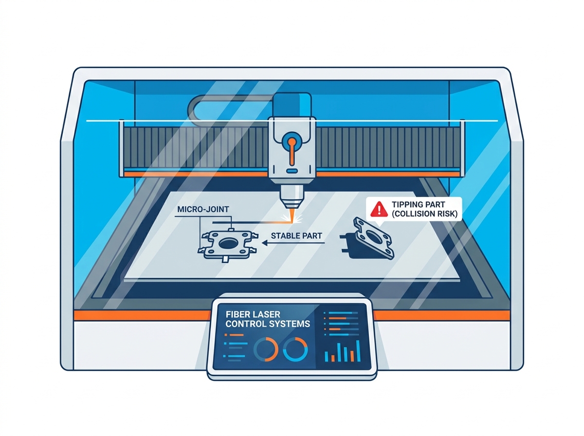
The tip-up phenomenon is the most dangerous event during thin-sheet laser processing. As the laser head travels along the final segment of a part's perimeter, the structural integrity of the surrounding skeleton releases residual internal stress. Simultaneously, the assist gas pushes downward and rebounds off the slats. This combination forces the unsupported edge of the part to pivot on its remaining axis, flipping vertically into the air. A part that was previously lying flat at 2mm thick suddenly presents a vertical obstacle that is 50mm or 100mm tall, sitting directly in the travel path of the high-speed optical head. The standard nozzle standoff distance is usually between 0.8mm and 1.2mm, leaving zero margin for error when a part tips.
When a part tips up, the consequences are immediate. Capacitive height sensors measure the electrical capacitance between the copper nozzle and the grounded sheet metal below them. They fail to detect the thin, vertical edge of a tipped part approaching from the side. The machine's Z-axis continues its rapid traverse across the sheet, completely unaware of the obstacle. The resulting high-speed collision transfers massive kinetic energy directly into the most delicate components of the machine. The copper nozzle crushes inward, the fragile ceramic sensor ring shatters, and the internal collimating lenses can misalign from the impact shock. The Z-axis motor simply cannot brake fast enough to prevent the impact.
Recovering from a crash requires a strict diagnostic framework for laser cutting head collision troubleshooting. You must follow a systematic approach to get the machine back online safely.
Trigger the emergency stop immediately and safely clear the tipped part from the cutting bed.
Jog the Z-axis upward manually to inspect the damage without dragging the head across the sheet.
Remove the copper nozzle and inspect the threads. If the orifice is deformed or out of round, discard it immediately.
Inspect the ceramic ring for hairline fractures. Even microscopic cracks will ruin the capacitive height sensing capability and cause erratic head diving.
Check the lower protective window for dust or spatter that may have been dislodged during the impact shock.
Run a full recalibration routine for the capacitive height controller to ensure the Z-axis tracks the material surface accurately.
Perform a tape shot test to verify that the laser beam remains perfectly centered through the nozzle orifice.
Not all unsecured parts cause collisions; many simply fall through the cutting bed. When small parts detach completely, gravity and gas pressure push them down through the gaps in the support slats. These parts land in the scrap drawers mixed with slag, dust, and skeletal remnants. Operators must then halt production, pull out the heavy scrap drawers, and manually sift through hazardous debris to retrieve the lost components. Parts that fall often suffer surface scratches or edge dents from hitting the slats, rendering them unacceptable for tight-tolerance applications. This hidden yield loss destroys material efficiency metrics.
The return on investment for programming micro-joints is massive. It takes mere seconds for a programmer to apply a micro-joint rule in the nesting software. Compare this minimal time investment against the thousands of dollars required to replace a shattered ceramic ring, a bent sensor body, or misaligned optics. Furthermore, the hours lost to machine downtime, troubleshooting, and recutting lost parts far outweigh the slight increase in denesting labor. Micro-joints act as a zero-cost insurance policy against catastrophic hardware failure. You protect your equipment, your material yield, and your production schedule simultaneously.
Modern fiber laser cutting control systems handle tab generation and spacing with remarkable precision. Software platforms act as the brain of the operation, translating CAD geometry into safe, executable machine code. These systems allow programmers to define specific rules for micro-joints based on material type, thickness, and part area. Instead of guessing where a part might fail, the software calculates the center of gravity and the aerodynamic profile to suggest the optimal tethering strategy. Operators can save these parameters into material-specific libraries, ensuring consistent application across multiple shifts.
Placing micro-joints manually on a complex nest of 500 parts is an invitation for human error. Manual placement often results in inconsistent spacing, forgotten tabs, and ruined edge quality when tabs are accidentally placed on critical mating surfaces. Auto-placement algorithms eliminate this inconsistency. Distance-based algorithms place a tab every set number of millimeters along a perimeter. Geometry-based algorithms are smarter; they analyze the shape of the part, avoid corners, and place tabs on long straightaways where they are easiest to remove and grind flat. Relying on auto-placement ensures that no small part is accidentally left unsecured.
Setting the correct parameters dictates the success of the entire operation. Joint width must scale with material thickness and type. You must adjust these settings carefully to avoid part failure.
For thin gauge steel (e.g., 1mm), a 0.2mm tab provides plenty of strength to resist gas pressure.
For thick plate (e.g., 10mm), you need a 0.5mm or 0.8mm tab to survive the heavy gas pressure and part weight.
A part under 50mm typically requires only a single tab placed on its longest edge.
Longer geometries require multiple tabs spaced evenly to prevent the part from twisting on a single pivot point.
Programmers must carefully position lead-ins and lead-outs away from the micro-joint. A pierce point creates a wider crater that will destroy a precise 0.2mm tab instantly.
High-end control systems now offer advanced features like smooth micro-joints or traceless nano-joints. Traditional tabs simply turn the laser off and on, leaving a distinct physical bump or burr on the edge. Traceless joints alter the laser power, frequency, and speed precisely at the tab location. Instead of leaving a full-thickness bridge of metal, the laser partially vaporizes the tab, leaving a microscopic, fragile connection. This ensures the part stays flat during cutting but breaks away perfectly clean during denesting, virtually eliminating the need for secondary grinding. The laser drops power to roughly 10% and increases frequency, creating a perforated line rather than a solid bridge.
Determining the exact tab size requires balancing material tensile strength, sheet thickness, and part weight. A tab that is too thin will vaporize under the heat of the laser, while a tab that is too thick will bend the part during manual breakout. Stainless steel is notoriously tough and requires smaller tabs than mild steel to allow for manual breakout. Aluminum is soft and requires slightly wider tabs to prevent premature failure. The table below outlines baseline starting parameters for standard processing.
Material & Thickness | Recommended Micro-Joint Width | Recommended Tab Frequency | Breakout Method |
|---|---|---|---|
Mild Steel (0.5mm - 1.5mm) | 0.15mm - 0.20mm | 1 tab per 100mm of perimeter | Manual shake / Twist |
Mild Steel (2.0mm - 4.0mm) | 0.25mm - 0.35mm | 1 tab per 150mm of perimeter | Rubber mallet / Pliers |
Stainless Steel (1.0mm - 3.0mm) | 0.15mm - 0.25mm | 1 tab per 120mm of perimeter | Twisting pliers |
Aluminum (2.0mm - 5.0mm) | 0.30mm - 0.45mm | 2 tabs minimum per part | Dead-blow hammer |
Heavy Plate (10.0mm+) | 0.60mm - 0.80mm | Every 200mm of perimeter | Mechanical leverage / Grinder |
Design for Manufacturability (DFM) principles dictate exactly where tabs should live on a part's geometry. Corners are universally poor locations for micro-joints. The laser naturally slows down at corners, concentrating heat. Placing a tab here causes excessive melting, and grinding a corner back to a sharp 90-degree angle is incredibly difficult for operators. Instead, advocate for placing tabs on long, straight edges. A straight edge allows an operator to quickly run a flap disc or belt sander over the remnant burr, restoring the edge quality in seconds without altering the part's critical dimensions. Inside contours should rarely have tabs unless the slug itself poses a tip-up risk.
The method used to remove parts from the skeleton depends entirely on the material thickness and the joint parameters. For thin sheets, the shake and drop method is highly efficient. Operators lift the entire skeletal sheet off the shuttle table, give it a firm shake, and the parts fall out intact onto a sorting table. For thicker materials, this is impossible. Operators must use dead-blow hammers to strike the parts out of the nest. Specialized twisting pliers can snap tabs cleanly without bending the parent material. In high-volume environments, automated part-sorting robots use suction cups to apply precise vertical force, snapping the tabs and stacking the parts automatically.
Denesting Tool | Best Application | Primary Risk |
|---|---|---|
Rubber Mallet | Medium gauge steel and aluminum | Can dent soft materials if struck too hard |
Twisting Pliers | Stainless steel and small intricate parts | Slow process for high-volume nests |
Oscillating Multi-Tool | Thick plate with heavy tabs | Consumes expensive cutting blades quickly |
Automated Suction Sorter | Lights-out manufacturing environments | Fails if tabs are too thick to snap vertically |
The primary risk in micro-joint implementation is the strength trade-off. You must engineer a joint strong enough to survive the violent cutting process, but weak enough to prevent part deformation during manual breakout. If a tab on a 1mm aluminum part is too thick, hitting it with a mallet will permanently bend the part before the tab breaks. Conversely, if a tab on a 10mm steel plate is too thin, the assist gas will blow it out mid-cut. Continuous testing and parameter adjustment are mandatory to find the perfect middle ground for your specific machine dynamics. Operators must communicate breakout difficulty back to the programming department to refine the software libraries.
Mapping specific software capabilities to actual operational outcomes reveals the true value of micro-joint optimization. Dynamic tab sizing directly reduces secondary grinding time. When the software automatically applies a 0.15mm tab to a delicate feature and a 0.4mm tab to a heavy structural edge on the same part, operators spend less time fixing mistakes. Smooth joint technology translates directly to faster denesting. When parts snap out cleanly without leaving sharp burrs, operators can handle them safely and move them straight to the press brake without routing them through a deburring station. This eliminates an entire step in the manufacturing routing.
As a fabrication facility scales from low-volume custom work to high-volume, lights-out manufacturing, micro-joint strategies must evolve. In a custom shop, operators can afford to tap out parts manually and grind edges. In a lights-out environment where the machine runs unattended overnight, manual grinding destroys profitability. Automation requires absolute predictability. The tabs must hold perfectly to prevent a crash at 2:00 AM, and they must interface seamlessly with automated unloading towers that drag the skeleton off the shuttle table. If a part sticks up, it catches the forks of the automated unloader, jamming an expensive automation cell and halting production until morning.
Keeping parts secured within the skeleton is a fundamental safety requirement. Unsecured parts left on the shuttle table create severe pinch hazards and laceration risks for operators tasked with clearing the bed. Reaching across a 5-foot by 10-foot table to grab loose, razor-sharp pieces of metal leads to hand injuries. If a loose part jams the shuttle table mechanism, it can cause catastrophic mechanical failure to the drive chains. By ensuring all parts remain tethered until they reach the designated sorting area, you protect your personnel from handling loose scrap and protect your equipment from internal mechanical jams.
Production managers must weigh the upfront time investment in programming against the long-term operational savings. Building a standardized micro-joint library in your nesting software takes a few hours of dedicated testing. However, this upfront work yields a massive reduction in scrap rates, extends the life of consumable nozzles and ceramics, and slashes secondary finishing labor. The total value of a well-executed micro-joint strategy is measured in increased machine uptime and higher overall throughput. You spend less time fixing crashes and more time cutting metal.
Conduct a standardized test cut on scrap material using varying tab widths (0.1mm to 0.5mm) and spacing intervals to establish a baseline library for the shop floor.
Audit your current nesting software settings to ensure auto-placement algorithms avoid corners and critical mating surfaces.
Train machine operators on proper denesting techniques using dead-blow hammers and twisting pliers to prevent part deformation.
Implement a strict preventative maintenance routine to inspect and recalibrate capacitive height sensors immediately following any suspected tip-up collision.
A: A micro-joint is an intentional, uncut section of material left along the cutting path. It acts as a physical tether, keeping the cut part connected to the main skeletal sheet until operators safely collect it during the denesting process. This prevents the part from shifting or tipping during the high-speed cutting cycle.
A: Tab width and frequency depend on material thickness, material type, assist gas pressure, and part geometry. Thicker materials and higher gas pressures require wider tabs and more frequent placement. For example, a 1mm steel part might need a single 0.2mm tab, while a 10mm plate requires multiple 0.6mm tabs to secure the part effectively.
A: Small parts tip up due to the aerodynamic lift generated by high-pressure assist gas entering the kerf. They warp because they lack adequate surface area to dissipate the intense localized heat generated by the laser beam. Proper tabbing anchors the part and provides a thermal bridge to dissipate heat into the skeleton.
A: By securing the part flat against the skeletal sheet, micro-joints prevent the part from flipping vertically into the machine's travel path. This ensures the material remains below the focal plane, keeping it safely out of the way of the high-speed optical cutting head and its delicate capacitive sensor.
A: Yes, most modern nesting software and control systems allow for rule-based, automated tab placement. These algorithms analyze part geometry to place tabs at optimal distances. They automatically avoid corners, lead-ins, and complex features to maintain edge quality while ensuring maximum part stability.
A: Removal depends on material thickness. You can often shake thin sheets manually so parts drop out onto a sorting table. Thicker materials require dead-blow hammers, specialized twisting pliers, or automated suction-cup sorting systems to snap the tabs cleanly without bending the parent material.
A: A traceless nano-joint is an advanced software-driven tab that alters laser power and speed at the joint location. Instead of leaving a solid bridge of metal, it partially vaporizes the connection. This minimizes the physical burr left on the edge, ensuring a clean breakaway and eliminating secondary grinding.


